


Well Manager
The Well Manager window offers the possibility to create, edit and delete groundwater or geothermal wells. Specifically, The Well Manager editor can control Well BC , Multilayer Wells and Borehole Heat Exchanger boundaries. The Well Manager editor can be accessed from the FEFLOW Edit menu or with the shortcut <Ctrl+W> as shown below.
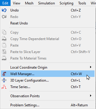
Well Manager access from Edit menu.
The Well Manager window presents itself as a list of already existing wells, if the model file doesn't contain any wells, the table is empty.
The entries in the table can be edited by clicking on their cells and modifying their values. Depending on the type of well, different columns (i.e., Properties of a well) can be edited. For example, the property Radius exists only for Multilayer Wells. The Properties that can't be edited are greyed out.
The following operations can be performed within the Well Manager:
Add Wells
The dropdown menu Add Well allows to create a nodal well (Well BC), MLW (Multilayer Well) or a BHE (Borehole Heat Exchanger) from coordinates or from a selection.
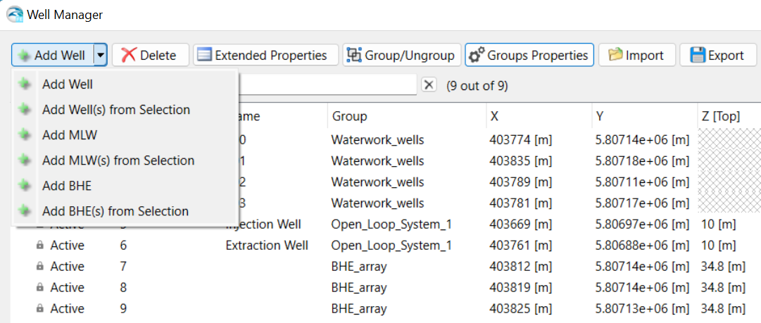
Menu to add wells.
Create Well BC from coordinates
-
Choose Add Well from the dropdown menu
-
Click on Add Well: a new entry will be created in the Well Manager and coordinates will be assigned such that the point will be located in the middle of the model domain (see Warning box below)
-
Change the coordinates and the other attributes manually and press Enter to apply the changes
-
Click on Verify if there are no conflicts, the well can be created (see Verify)
-
Click on Apply and OK: the Well BC is created in the domain
Notice that the X-coordinate has been modified by the well manager to match the one of the closest existing node. For more informations, see the definition of the Nearest node distance in the Well Manager Global Settings.
|
|
Using Add Well or Add MLW or Add BHE, FEFLOW will initially assign coordinates that correspond to the middle of the model domain. The user is responsible to change coordinates manuallyto the correct location of the well. |

Create Well BC from selection
-
Select a node corresponding to the location of the desired Well BC
-
Choose Add Well(s) from Selection from the dropdown menu
-
Click on Add Well(s) from Selection: the new entry is created in the Well Manager
-
Change the Well BC attributes and press Enter to apply the changes
-
Click on Verify, Apply; and OK: the Well BC is created in the domain
The procedure to create MLWs and BHEs is analogous to the one just explained for Well BCs, with different attributes to be assigned.
Notice that for models including flow and transport of mass and/or heat, Well BCs, MLWs and BHEs can be associated to other boundary conditions - for example, an injection well could be associated to an injection of mass through a Mass-oncentration BC. In this case, the Well Manager offers the possibility to select different combinations of boundary conditions in the Well Type column:
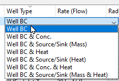
Well Types for Well BC.
Delete Wells
To delete wells, select the corresponding rows in the Well Manager and click on Delete, as shown below.
Multiple entries can be deleted at the same time.
In order to undo, click on the Reset button below.
Extended Properties
Activating the Extended Properties will add additional columns to the Well Manager, highlighted in the figure below.
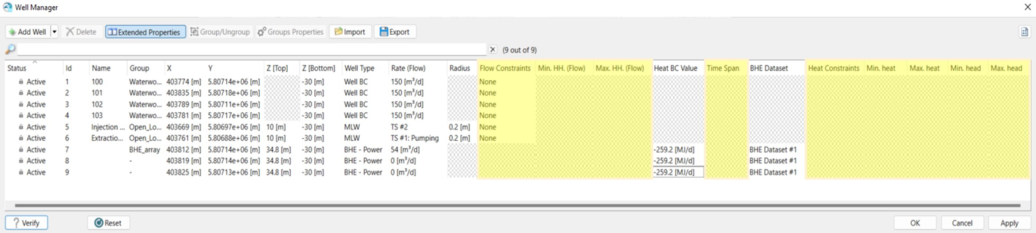
Extended Properties of the Well Manager.
Most of the new columns are relative to constraints, while the column Time Span can be only applied to BHEs with Energy input data (see BHE Editor ).
Please, notice that if the model contains transport of mass, corresponding constraints will be also available, as shown below.
The
constraints available are the standard FEFLOW constraints that can also
be found the  Data
panel.
Data
panel.
Group/Ungroup
Wells or BHE can be grouped and assigned shared properties. A group can consist of only either Wells, MLWs or BHEs.
In order to group wells, a selection of rows in the Well Manager is to be made and with a click on Group/Ungroup the wells can be given a group name or added to an existing group.
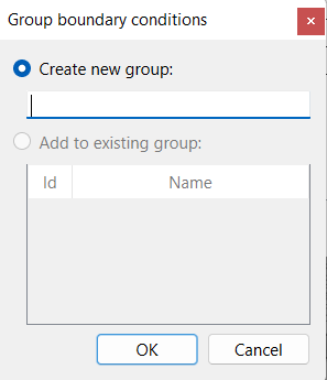
Grouping Wells.
Once the group has been named, Apply needs to be clicked before group properties can be assigned.
Groups Properties
Rules and properties can be assigned to a group, depending on the type of group (Wells, MLWs or BHEs). Rules are heading properties, as for example the rule Open Loop, which can have the property Temperature Difference assigned. A list of rules can be found below.
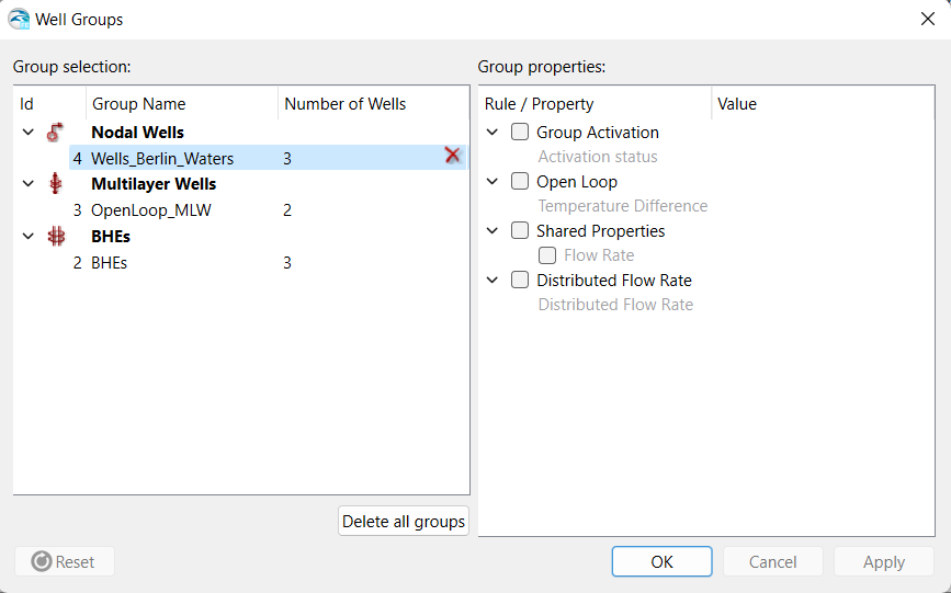
Group rules and properties of nodal wells.
Group Activation
All wells of a group can be deactivated, per default they are active.
Shared Properties
All wells of a group can be assigned shared properties, such as Flow Rate and Radius for MLW and Wells and additionally Input Type, Input Value and BHE Dataset for BHE.
Distributed Flow Rate
This rule is only available for Wells and MLWs. The given distributed flow rate is assigned to each participating well, after being divided by the number of wells in the group.
Closed Loop
With the rule Closed Loop, BHE arrays can be created inside the Well Manager. The type of connection (serial, parallel, custom) needs to be defined in the property Pattern. The options Serial and Parallel will connect all members of the group accordingly. If a user-defined arrangement is to be implemented, Custom pattern needs to be selected and the connections between the BHE need to be defined in the BHE Interconnection Editor.
The remaining parameters Flow Rate, Input Type, Input Value and Time Span describe the array's properties.
Open Loop
Wells that are part of an Open Loop geothermal system can now be linked in the Well Manager. This rule is only available in models with a Heat Problem Class. FEFLOW detects the injecting wells of the group and assigns a Temperature BC there, which corresponds to the average temperature at the pumping wells plus the temperature difference entered as property Temperature Difference under the Open Loop rule. The temperature difference can be a constant value or a time-series.
Import
|
|
Tables are automatically imported in FEFLOW default units. Please refer to Default Values. |
Through Import, large datasets of wells can be imported from a common set of FEFLOW-map types (see figure below for allowed file formats).
The names of the columns imported need to correspond to the headers of the Well Manager columns. Additional columns as corresponding to those contained in the Extended Properties can be optionally imported.
If the imported dataset contains formal mistakes, the Well Manager triggers a Warning message containing the erroneous fields that could not be imported correctly.
|
|
Imported datasets can be either appended to the existing wells or substitute the existing ones. You can chose the default behaviour or opt to be asked every time in the Well Manager Global Settings. |
|
|
Be aware that Time Series Ids require a separate column to be imported correctly. To be sure of the format, please export the Well Manager table once as example. |
Export
By clicking on the Export button, the content of the Well Manager can be exported to a common set of FEFLOW-map types (see figure below for allowed file formats).
|
|
Extended properties are exported only if visible in the Well Manager. |
Search Bar
The search bar can be used to search for particular wells by their names or attributes, as shown below.
The number of results is shown next to the bar.
Verify
After modifying the Well Manager window (e.g., having added a new well), the user can click on the Verify button to check if there is a problem in the new definition. If there are no problems, a green symbol appears next to Verify :
"Verify" procedure succeeded.
On the other hand, if any problem arises, a red error symbol appears next to the Verify button and the problematic entry is highlighted in red:
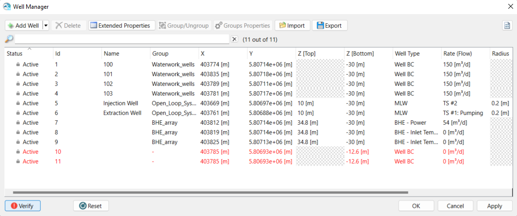
"Verify" procedure failed.
The user can then hover the mouse on top of the highlighted entry, and a message will appear to explain the cause of the conflict.
Possible sources of conflicts can be:
-
FEFLOW can't find a node for the assignment (as shown above).
-
Increase the Nearest Node Distance in the Well Manager Global Settings.
-
Click on Apply
-
The well will be created correctly if the distance is large enough
-
The Well created is overlapping with an existing one.
-
Change the coordinates and Verify again
-
Click on Apply
-
The well will be created correctly
Reset
The reset button allows the user to revert to the last saved version of the Well Manager.
Well Manager Global Settings
Global Settings can be defined for the Well Manager from the symbol in the upper right corner. GLoabl Settings refer to:
-
Nearest node distance: Radius around a given coordinate in which FEFLOW searches for a node for the assignment of wells.
-
Import behaviour: When importing a well dataset, wells can be appended to the existing ones or they can delete the ones already present. The user can define the default choice in the Global Settings panel, or choose to be asked every time.
For more details, please head to Global Settings .