


Finite-Element Mesh
Spatial Discretization
This section describes the generation of finite-element
meshes (2D or 3D domains). During model parametrization ( Data panel in FEFLOW), material
information is assigned to the finite elements (triangle, quadrilateral,
prism, cuboid, tetrahedral, hexahedra and pyramid). System of equations
to solve the process variables (hydraulic head, mass concentration, temperature,
mean groundwater age, mean lifetime expectancy and exit probability concentration)
are based on each node of the finite-element mesh.
Data panel in FEFLOW), material
information is assigned to the finite elements (triangle, quadrilateral,
prism, cuboid, tetrahedral, hexahedra and pyramid). System of equations
to solve the process variables (hydraulic head, mass concentration, temperature,
mean groundwater age, mean lifetime expectancy and exit probability concentration)
are based on each node of the finite-element mesh.
The denser the mesh the better the numerical accuracy,
and the higher the computational effort. Numerical difficulties can arise
during the simulation if the mesh contains too many highly distorted elements.
Thus, some attention should be given to the proper design of the finite-element
mesh. For transport simulations, the Péclet criterion can be useful for
determining the required mesh density. The Péclet Number is
available as elemental distribution in Auxiliary Data section
in the Data
panel. To assist in creating a well-shaped mesh, FEFLOW offers
various tools, including local refinement and derefinement of the mesh
and (selective) mesh smoothing. Local refinement during mesh generation
will typically lead to a better mesh quality than later subdivision of
elements.
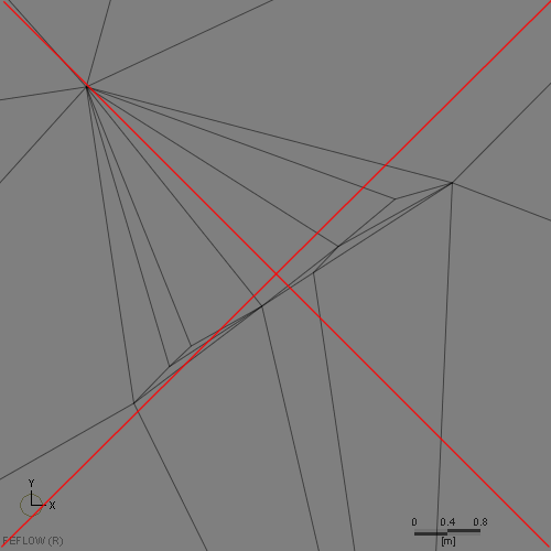
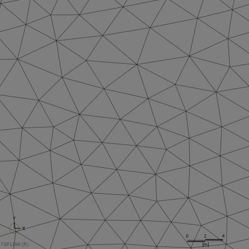
Examples for bad and good mesh geometry.
FEFLOW 8.1 supports a number of different meshing options. For all 2D applications as well as 3D meshes based on layered meshing, a 2D finite-element mesh is defined. For 3D applications, this is then expanded in the z direction into a layered mesh, which then may be further developed into a partially unstructured mesh by re-meshing parts of the domain or by pinching layers. For fully unstructured meshes, a 3D Supermesh is imported, and an unstructured 3D mesh is generated from this. These operations for 3D applications are discussed in detail in section 3D Meshing.
Mesh Property Check
FEFLOW provides some basic tools to check the
properties of a finite-element mesh, which are accessible via Auxiliary
Data in the
Data
panel. The following parameter distributions can be shown in the
currently active view:
|
Geometrical Information (2D models) |
Geometrical Information (3D models) |
Physically-Based Information |
|---|---|---|
| Elemental areas | Elemental diameters | Péclet Number |
| Max. interior angle of triangles or quadrangles | Elemental volumes | Courant Number |
| Delaunay criterion violations | Slice distance (only for layered models) | |
| Condition number | Nodal distance (only for layered models) | |
| Layer thickness (only for layered models) | ||
| Min. dihedral angle of tetrahedrons | ||
| Max. dihedral angle of tetrahedrons | ||
| Condition number |
The parameter distributions of Péclet Number and Courant Number are calculated and updated at each time step during the simulation.
Distances and areas in Slice and Supermesh views and distances in 3D views can be measured using the Measure tool. If the Supermesh is the active view, the Measure tool is located in the Mesh-Editor toolbar. For active Slice views, the tool is accessible via the Inspection toolbar.
For checking the mesh quality in the entire model
or parts of the domain (elemental selections), the option to show descriptive
statistics on the above listed parameters can be very useful (available
in the context menu of the parameters in the Data
panel).
As example, a comparison of the histograms for two different options of mesh generation is shown below. The closer the maximum interior angles are to 60° and the lower the condition number, the better the overall mesh quality. Example demonstrates the result of the 2D Mesh Smoothing (with X-Y inheritance in 3D tool.
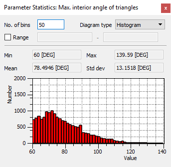
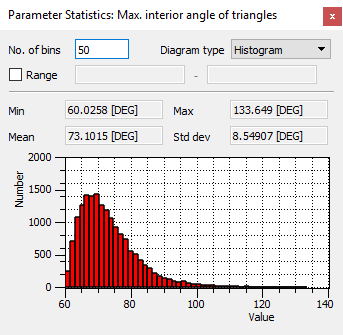
Parameter Statistics for Max. interior angle of triangles or quadrangles. Left and right images are the before/after the smoothing operation.
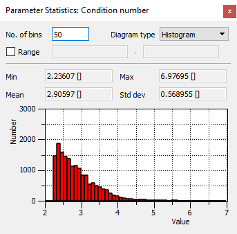
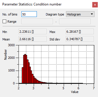
Parameter Statistics for Condition number. Left and right images are the before/after the smoothing operation.
Analog to the 2D case, FEFLOW 8.1 has tools for the improvement of the mesh quality in 3D domains (see 3D Mesh Editing).
Mesh-Element Deactivation
By default all mesh elements are active and results
are computed at each mesh node. Using the In-/active Elements parameter
in the Geometry section of the
Data panel,
elements can be deactivated for the entire simulation period or only for
specific time steps during a simulation run. In case that all elements
surrounding a mesh node are inactive, FEFLOW does not compute results
at this node. With this option, time-varying geometries as well as impermeable
structures can easily be considered.
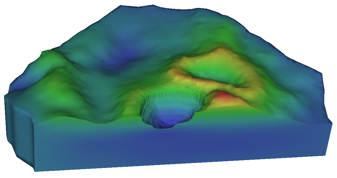
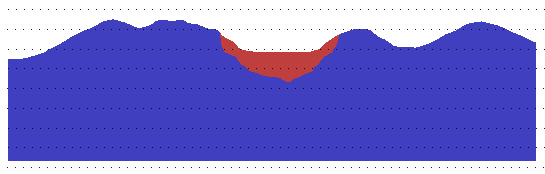
Example of element deactivation in a 3D model. Approach is used to simulate a time-varying excavation of an open-cast mine. Note that 3D has been clipped in FEFLOW to appreciate better the geometry.
In 3D models, the parameter In/outflow on top/bottom is applied to the first set of active elements if elements within the top layer (s) are set to inactive. This ensures that assigned recharge or evapotranspiration values are passed on to deeper locations of the model domain correctly.
 |
In/outflow on top/bottom is not available in models with partially or fully unstructured mesh. In these cases, a Neumann boundary condition (Fluid-flux BC) has to be used instead. This cannot be automatically inherited to the elements below in case of element deactivation! |
Geotransformation
FEFLOW 8.1 expects all attached maps and the model itself to share the same coordinate system. Maps using differing coordinate systems can be transformed in advance using the external software WGEO, which is part of the FEFLOW software package.
In case that a geotransformation of the model
itself is necessary, the Geographic Transformation option
in the  Mesh-Geometry
toolbar can be used.
Mesh-Geometry
toolbar can be used.